10MHz clock
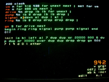
This code from block 942 is loaded into node 200 which has I/O pin 18. A 10MHz ceramic resonator is to be connected from pin to ground. This non-linear drive strategy needs only 1 pin and uses minimal energy to maintain oscillation.
A resonator has a lower Q than a crystal and is much easier to start oscillating. It's plenty accurate for video. Pin 18 can be waited on by reading the left port, though nothing useful is returned.
Node 200 talks to node 300 via their down ports. 300 will use the clock to generate video framing signals. Code for 200 is loaded last since when it starts, all other nodes will be activated.
us
us will delay a number of microseconds. The number of unexts in a us may need to be adjusted for different chips or temperatures. An oscilloscope is necessary for accurate determination.
ms
ms will delay a number of milliseconds. The number of unexts in us may be different if accurate ms timing is desired.
Neither us or ms is used here. I leave the code in clock as a reference copy that I may be able to find.
go
go, as usual, describes the strategy of running the clock. It generates 10 drive signals to start the oscillator. Then enters an infinite loop in which it lets the oscillator ring once, then pumps it once; each time sending a signal thru the down port. Of course, it's important the node 300 respond quickly to that signal.
init
After setting registers a and b, the numbers 7 0 20000 800 6 0 30000 0 are left on the stack. This fills the stack with 2 sets of 4 numbers that are used by drive, pump and ring. dup dup drop drop assures the 10-position stack is full.
drive
Discards the first number (800 or 0), writes the next 2 to io (20000 0 or 30000 0) to pulse the oscillator high (low) then tri-state. Uses the last (7 or 6) to delay and fill the 50 ns half-period. Drive is called an even number of times (10) to start oscillation (5 cycles).
pump
Sets the wake-up direction (800 low or 0 high) and reads the pin, waiting for the transition (going low or going high). Then pulses the oscillator and discards the 4th number. The pin input has hysteresis, so the transitions are roughly 1000 mV going high and 800 mV going low. The drive pulse occurs near the peak. Pump is called an even number of times.
ring
Sets the wake-up direction (800 low or 0 high) and waits for the transition. Ring is called an even number of times.
signal
Saves and restores the a register. Sends a number to the down port to wake-up node 300.